Relay Contacts Symbol

Relay contacts symbol
What is a contact relay?
A switch or relay contact designed to move laterally with a wiping motion when engaging with or disengaging from a mating contact. From: Modern Dictionary of Electronics (Seventh Edition), 1999.
What is the symbol for a contactor?
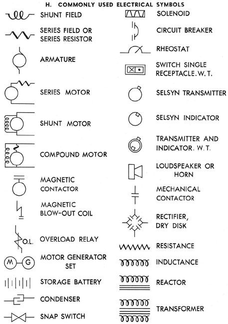
The contactor is designated as K and, in the coil symbol, the K1/4 indicates that there are four associated contacts. Sometimes the coil designation is placed beside the coil symbol. In this case there are three normally open power contacts, and one normally open control contact.
What are the 3 terminals on a relay?
Terminal Descriptions
- -COIL- This the is the COIL terminal. These are the terminals where you apply voltage to in order to give power to the coils (which then will close the switch).
- -NO- This is Normally Open switch. ...
- -NC- This is the Normally Closed Switch. ...
- -COM- This is the common terminal of the relay.
What is the function of contactor?
Summary. A contactor is a special type of relay used for switching an electrical circuit on or off. They are most commonly used with electric motors and lighting applications.
What is relay function?
1. The relay permits a small amount of electrical current to control high current loads. When voltage is supplied to the coil, small current passes through the coil, resulting in a larger amount of current passing through the contacts to control the electrical load.
What type of contacts are used in relay?
Electrical Relay Contact Configurations For example, a contact which is normally open in the de-energised position of the relay is called a “Form A contact” or make contact. Whereas a contact which is normally closed in the de-energised position of the relay is called a “Form B contact” or break contact.
How many contacts does a relay have?
A relay consists of at least two contacts and an excitation coil. These contacts may be normally open or normally closed. These contacts are closed or opened by exciting the coil. Relays are used for switching of control circuits and cannot be used for power switching with relatively higher ampacity.
What are front and back contacts of relay?
Relays or switches that are normally open and close upon operation are called NO contacts. They are also called front contacts. Relays or switches that are normally closed and open upon operation are called NC contacts. They are also called back contacts.
What is the difference between contactor and relay?
Relays are used to control contacts of an electrical circuit due to a change of parameters or conditions in the same circuit or any other associated circuit. Contactors, on the other hand, are used to interrupt or establish connections in an electrical circuit repeatedly under different conditions.
What is K symbol in electrical?
K for relays and contactors. V for tubes and semiconductors. (Consider “V” for “vacuum tube”.) Q for “switching devices for power circuits”, i.e. circuit breakers.
What is normally open contact?
Normally open - Is a contact that does not flow current in its normal state. Energizing it and switching it on will close the contact, causing it to allow current flow. Normally closed - Is a contact that flows current in its normal state.
Why does a relay have 3 pins?
A normally closed relay will switch power OFF for a circuit when the coil is activated. 5 pin relays provide 2 pins (85 & 86) to control the coil and 3 pins (30, 87 & 87A) which switch power between two circuits.
How are relays labeled?
Although most relays are labeled at the bottom, you can always find the 30 pin set perpendicular to pins 87 and 87a for easy identification to the power source. Realizing that 85 and 86 are the coil pins, these pins will be transferring the current through the coil.
What pins to jump on relay?
The fuel pump primes when the ignition switch is in run. If you want to jump the fuel pump relay it will be pin 30 to 87.
What is L1 and T1 on a contactor?
The L1, L2, and L3 terminals are where the power wires connect to the contactor. The T1, T2, and T3 terminals are where the device wires connect to the contactor. The L1 contact connects to the T1 contact, the L2 contact connects to the T2 contact, and the L3 contact connects to the T3 contact.
How do you test a contactor?
Put one lead on either side. And then push the middle that tells you that this side is good move to
What is A1 and A2 in contactor?
A1 and A2 on a contactor typically refer to either end of the electromagnetic coil assembly. Most contactor manufacturers use A1 and A2 to designate the two terminals connecting electrical power to the contactor's magnetic coil.
What are the 5 applications of relay?
Applications of Relays in Electronic Circuits
- Relay Drive by Means of a Transistor.
- Relay Drive by Means of SCR.
- Relay Drive from External Contacts.
- LED Series and Parallel Connections.
- Electronic Circuit Drive by Means of a Relay.
- Power Source Circuit.
- PC Board Design Considerations.
How do you test a relay?
Grab a multimeter and set it to Ohms. Touch the leads across the electromagnet coil pins and measure resistance. Anywhere from 50-120 ohms is OK. Out of range or open means a bad electromagnet coil winding and time for a new relay.


Post a Comment for "Relay Contacts Symbol"